First inversion of Single Slider crank chain :
Pendulum pump or bull Engine or Hand Pump
In this mechanism, the inversion is obtained by fixing the cylinder or link 4 (i.e. sliding pair), as shown in Fig.
In this case, when the crank (link 2) rotates, the connecting rod (link 3) oscillates about a pin pivoted to the fixed link 4 at A and the piston attached to the piston rod (link 1) reciprocates.
The duplex pump which is used to supply feed water to boilers have two pistons attached to link 1, as shown in Fig.
Second inversion of Single Slider crank chain :
Oscillating cylinder Engine
The arrangement of oscillating cylinder engine mechanism, as shown in Fig., is used to convert reciprocating motion into rotary motion.
In this mechanism, the link 3 (Connecting Rod) forming the turning pair is fixed. The link 3 corresponds to the connecting rod of a reciprocating steam engine mechanism.
When the crank (link 2) rotates, the piston attached to piston rod (link 1) reciprocates and the cylinder (link 4) oscillates about a pin pivoted to the fixed link at A.
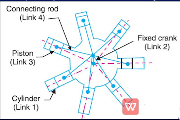
Third inversion of Single Slider crank chain :
Rotary internal Combustion Engine or Gnome Engine Sometimes back, rotary internal combustion engines were used in aviation. But now-a-days gas turbines are used in its place.
It consists of seven cylinders in one plane and all revolves about fixed centre D, as shown in Fig., while the crank (link 2) is fixed.
In this mechanism, when the connecting rod (link 4) rotates, the piston (link 3) reciprocates inside the cylinders forming link 1.